Measuring Power Factor with a Clamp Meter: A Practical Guide
A basic clamp meter tells you how much current is flowing. A power clamp meter tells you how usefully that current is being used. Knowing the difference matters the moment you need to diagnose a lagging motor, verify a capacitor bank installation, or confirm that a facility is avoiding power factor penalty charges. This guide walks through the equipment options, the measurement procedure, and what to do with the numbers you get.
At a Glance
- Standard clamp meters read current only; power clamp meters add a voltage lead and phase-angle detection to compute W, VA, VAR, and PF.
- Single-phase measurement needs one voltage connection and one current clamp; unbalanced three-phase loads need per-phase readings summed, not averaged.
- Live electrical measurement work requires proper PPE and, per NFPA 70E guidance, an awareness of arc-flash risk, not just shock risk.
- A reading of PF greater than 1.00 always signals a wiring or reference error, never a real measurement.
- Mid-range power clamp meters run about $250 to $600 and typically specify PF accuracy of plus or minus 0.02 to 0.03 under sinusoidal conditions.
- On loads with significant harmonic distortion (VFDs, LED drivers), a power quality analyzer with harmonic decomposition outperforms a basic power clamp.
Basic Current Clamps vs. Power Clamp Meters
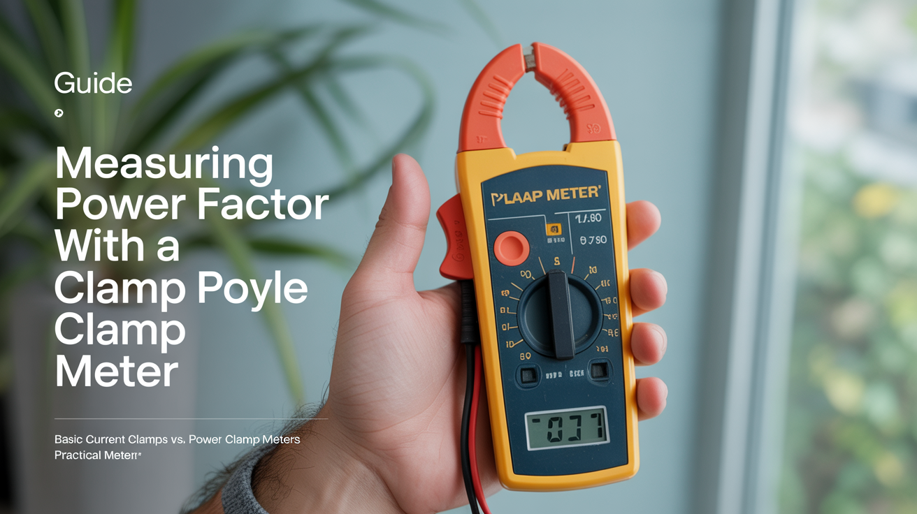
A standard clamp meter measures RMS current by sensing the magnetic field around a conductor. Wikipedia's article on current clamps describes several sensing technologies behind this, including Hall-effect sensors (which read both AC and DC) and current-transformer clamps (AC only), but a basic unit like this has no awareness of voltage or phase relationship, so it cannot report power factor at all. You get amperes, nothing more.
A power clamp meter adds a voltage input lead and internal phase-angle detection circuitry. By sampling both the voltage waveform and the current waveform simultaneously, it calculates the phase displacement between them, using the same underlying principle Wikipedia describes for power meters generally: "true power is the product of the instantaneous voltage and current integrated over a cycle." From that integration it derives:
- True power (W), the real work done
- Apparent power (VA), the total current demand on the supply
- Reactive power (VAR), the non-working component
- Power factor (PF), the ratio W divided by VA, expressed as a decimal or percentage
Some high-end units also display the displacement power factor angle in degrees and flag whether the load is leading or lagging.
| Meter Type | Current | Voltage | Power (W) | PF | Harmonics |
|---|---|---|---|---|---|
| Basic clamp meter | Yes | No | No | No | No |
| True-RMS clamp meter | Yes | No | No | No | No |
| Power clamp meter (entry) | Yes | Yes | Yes | Yes | No |
| Power quality analyzer | Yes | Yes | Yes | Yes | Yes |
For routine power factor checks on motors and lighting panels, a mid-range power clamp meter costing $250 to $600 is sufficient. Power quality analyzers are worth the extra expense when harmonic distortion is suspected, because distortion skews apparent power in ways a basic power clamp cannot separate.
Safety Before You Start
Live electrical measurements carry serious risk, and the danger is not limited to electric shock. Wikipedia's arc flash article notes that arc temperatures "can reach or exceed 35,000 degrees Fahrenheit (19,400 degrees Celsius) at the arc terminals," hot enough to vaporize copper and produce a pressure wave alongside the thermal hazard. The same article points to NFPA 70E as the governing framework in the United States, explaining that it "provides guidance on implementing appropriate work practices that are required to safeguard workers from injury while working on or near exposed electrical conductors," including tables that map specific tasks and voltage levels to a required category of PPE.
All work described here must be performed by a qualified electrician or electrical engineer wearing appropriate PPE: insulated gloves rated for the system voltage, safety glasses, and arc-flash-rated clothing where required by the arc hazard analysis for that panel or conductor. Never open energized enclosures beyond the scope of your authorization or local regulations.
Single-Phase Power Factor Measurement
Single-phase measurement is the most straightforward application. The steps below apply to a 120 V or 240 V branch circuit.
Equipment you need
- Power clamp meter with voltage leads
- Rated test leads and alligator clips
- Personal protective equipment
Procedure
- Identify the circuit. Confirm the nominal voltage and ensure the conductor insulation is intact and accessible.
- Connect the voltage leads. Clip the red lead to the line conductor (or a live terminal in the panel) and the black lead to neutral. The meter establishes its voltage reference from this connection.
- Clamp the current jaw around the line conductor only. Clamping around both line and neutral cancels the fields and gives a zero reading.
- Set the meter to power measurement mode. Most meters display W, VA, VAR, and PF simultaneously once a stable signal is acquired.
- Allow 10 to 15 seconds for the reading to stabilize, especially on motor loads that cycle.
- Record W and VA alongside PF. Cross-checking them yourself is a good habit, PF should equal W divided by VA.
Three-Phase Measurement
Three-phase loads require either multiple single-phase readings or a meter with a three-phase measurement mode. The approach depends on the load balance.
Balanced three-phase loads
For motors and other symmetrical loads, measuring one phase and multiplying total three-phase power by three is acceptable as an approximation. PF is the same on all three phases when the load is balanced, so a single-phase reading gives the system PF directly.
Unbalanced three-phase loads
Panel boards supplying a mix of single-phase circuits are almost never perfectly balanced. Here you need to measure each phase separately, sum the real power across phases, sum the apparent power across phases, and then compute overall PF:
PF (system) = (W1 + W2 + W3) divided by (VA1 + VA2 + VA3)
Do not average the three individual PF readings, that arithmetic is incorrect when the phase loads differ.
Some power quality analyzers accept three current clamps and three voltage leads at once, computing system PF in real time. That is the preferred method for permanent monitoring installations. For the underlying line-to-line and per-phase formulas these instruments apply, see Power Factor in Three-Phase Systems.
Worked Example: Deriving PF from Measured W and VA
Suppose you clamp a 240 V single-phase motor feed and the meter displays:
- True power: 1,840 W
- Apparent power: 2,300 VA
Power factor = 1,840 divided by 2,300 = 0.80
That is a lagging PF of 0.80, which is typical for an induction motor running at partial load. The relationship between watts, VA, and VAR tells you the reactive component: VAR = square root of (2,300 squared minus 1,840 squared) ≈ 1,380 VAR. To correct this to 0.95 PF, a capacitor bank would need to supply roughly 960 VAR on that circuit.
If your meter gives you only W and VA and you need to confirm the figure against published specs, the calculate power factor from watts and VA method applies directly.
Reading the Display Correctly
Power clamp meters differ in how they present results, and misreading the display is a real source of error.
Decimal vs. percentage. Some meters show PF as 0.85; others show 85. They mean the same thing. Check the user manual.
Leading vs. lagging indicator. A capacitive load produces a leading PF; an inductive load (motors, transformers) produces a lagging PF. Many meters flag this with an "L" or "C" symbol. A power factor meter overview covers the display conventions in more detail.
Averaging mode. Motors have high inrush current on start-up that temporarily depresses PF. Meters with averaging or hold functions let you capture steady-state values rather than the transient spike.
Auto-range vs. manual range. On high-current conductors above 400 A, confirm the clamp jaw rating. Exceeding it does not just give a wrong answer, it can damage the meter and, in a worst case, create an arc-flash hazard if the jaw fails to close properly around an energized conductor.
Troubleshooting Common Display Problems
| Symptom | Likely cause | What to check |
|---|---|---|
| PF reads above 1.00 | Voltage and current leads on different phases | Confirm both leads reference the same phase conductor |
| PF reads exactly 1.00 on a known motor | Meter lost voltage reference | Re-check voltage lead contact; look for a low-battery or fault icon |
| Reading flutters continuously | Cycling load (HVAC compressor, VFD ramp) | Use averaging or peak-hold mode; note load state at time of reading |
| W and VA don't match displayed PF | Firmware rounding or stale hold value | Take a fresh reading rather than relying on a held display |
| Very low PF on a lightly loaded motor | Normal magnetizing-current behavior at light load | Compare against the motor's rated-load PF, not an assumed constant |
When the Reading Looks Wrong
A PF above 1.00 is physically impossible. If you see it, the voltage and current leads are not sampling the same phase, swap the voltage reference to the correct phase leg. A PF of exactly 1.00 on a motor is also suspicious; more likely the meter has lost its voltage reference and is defaulting to unity.
PF readings that flutter continuously suggest a load cycling on and off (HVAC compressors, for example) rather than a meter fault. Use the averaging function or take a peak-hold reading and note the load condition at the time.
For background on what power factor actually represents, revisiting the fundamentals can help interpret unusual readings in the field.
Frequently Asked Questions
Can a standard clamp meter measure power factor?
No. A standard or true-RMS clamp meter measures current only. It has no voltage input and no phase-angle detection, so it cannot calculate power factor. You need a power clamp meter or power quality analyzer that accepts voltage leads alongside the current clamp.
How accurate are power clamp meter PF readings?
Mid-range power clamp meters typically specify PF accuracy of plus or minus 0.02 to 0.03 at full scale under sinusoidal conditions. Accuracy degrades on highly distorted waveforms because the meter assumes a fundamental-frequency relationship between voltage and current. If total harmonic distortion exceeds 5 to 10%, a power quality analyzer with harmonic decomposition gives a more reliable result.
Do I need to de-energize the circuit to use a power clamp meter?
No. The clamp jaw goes around the conductor without breaking the circuit, and the voltage leads clip onto accessible terminals. The measurement is performed live. That is precisely why proper PPE and adherence to safe work practices, including an arc-flash risk assessment for the panel in question, are required rather than optional.
What power factor should a motor read under normal conditions?
Most induction motors run between 0.75 and 0.90 PF at rated load. PF drops further at partial load, sometimes to 0.5 or below at under 25% load. If a motor that historically read 0.85 now reads 0.65 under the same mechanical load, that shift warrants investigation, it can indicate a winding fault or supply voltage imbalance.
Can I use a power clamp meter on a panel without an arc-flash label?
Treat the absence of a label as a reason for more caution, not less. A missing or outdated arc-flash label usually means no incident-energy study has been done recently, not that the hazard is absent. Standard practice is to assume worst-case PPE for the voltage class until a qualified person can verify the panel's actual arc-flash category, rather than proceeding on the assumption that no label means no risk.